
The drive keeps tripping on ground fault, but the motor megs clean. What is tripping it?
VFD ground fault trips when the motor tests fine: what the drive is actually measuring
Short answer
A drive does not detect a ground fault the way a breaker does. It sums its own three output currents and faults when the residual passes a threshold set around 5 percent of drive rated current, far more sensitive than anything upstream. Capacitive current flows from the motor cable to ground on every switching edge and grows with cable length and carrier frequency, so a long run on a high carrier holds that residual near the threshold with nothing broken. Megging a motor through a connected drive tells you nothing and can destroy the output stage. Disconnect at the drive, test cable and motor separately at 500 volts DC, and readings above the IEEE 43 floor of 5 megohms mean leakage, not a fault.
The call is always a version of the same story. The drive faults on ground fault, the motor megs clean, so the drive gets swapped. Then the new drive does it too. Ground fault on a drive is not the measurement most people assume it is, and once you know what the drive watches, the fault finding stops being guesswork.
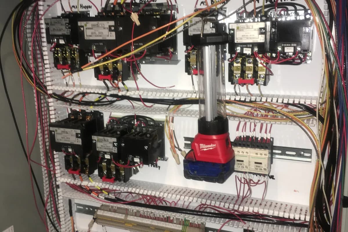
How a drive decides it has a ground fault
A breaker ahead of the drive sees phase currents and trips on too much of them. The drive works from the other end. It measures its three output currents, adds them, and faults when what is left over passes a fixed threshold. In a healthy circuit they sum to zero, so any remainder went to ground.
The threshold is small, commonly around 5 percent of drive rated output current, so a drive rated 17 amps can fault on roughly 0.8 amps of residual, and on most units it is not adjustable. The NEMA application guide for AC adjustable speed drive systems makes both points, and lists parasitic capacitance from long motor cables or cables sitting in water alongside a genuine phase to ground short.
So a clean megohm reading does not clear the circuit. It says the insulation has not broken down under steady DC, and nothing about what that circuit does under thousands of switching edges a second.
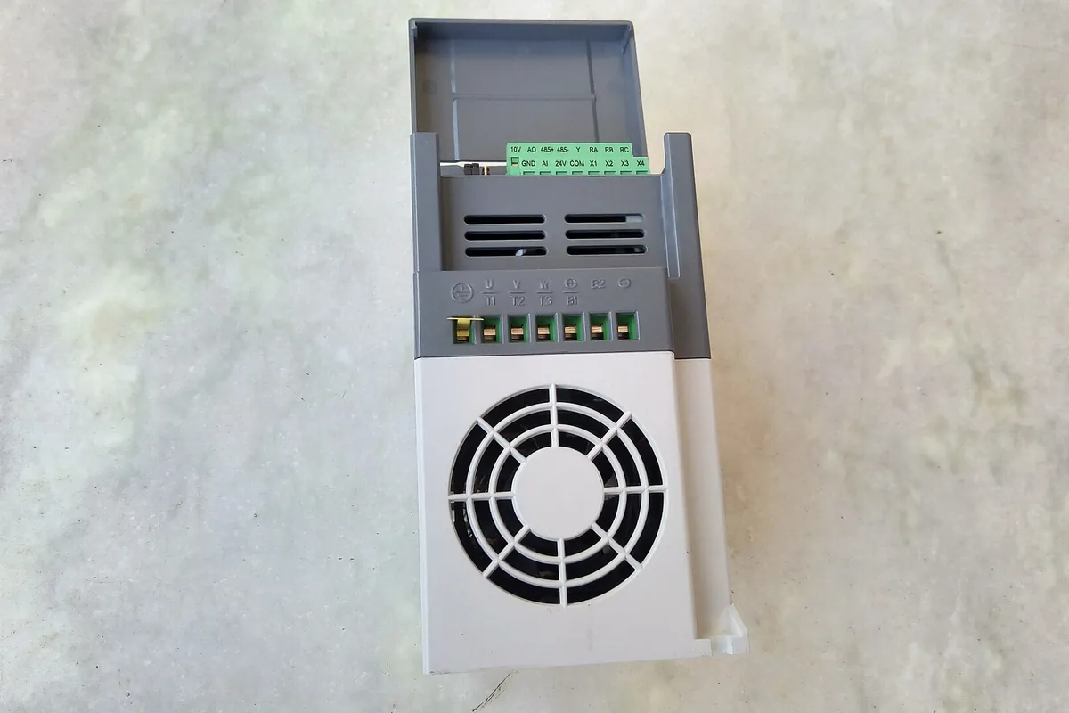
The cable makes most of the leakage
Every conductor has capacitance to what surrounds it: shield, conduit, tray, earth. At 60 Hz that hardly matters. The drive output is a train of steps rising to full bus voltage in roughly 50 to 100 nanoseconds, and current through a capacitance depends on how fast the voltage changes, not how high it is. Every edge pushes a pulse into ground, and the drive counts all of them.
Both terms scale predictably. Capacitance is per unit length, so 300 feet of cable leaks about three times what 100 feet leaks, and edges per second follow the carrier, so 8 kHz moves roughly twice the charge 4 kHz does. A drive that ran for years on an 80 foot run at 4 kHz can start faulting the week the motor moves to the far wall.
The pattern gives it away. Leakage trips come on acceleration, in one speed band, or on the run command at a high carrier, and they barely care how loaded the machine is. A real insulation fault is more repeatable and shows in the megohm reading. What a drive actually does covers the switching that makes these edges.
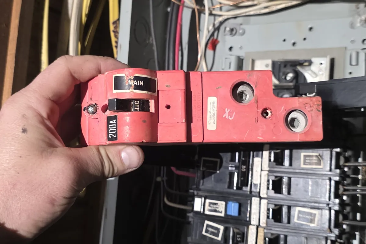
Working the fault in order
The expensive version of this job is a parts swap in the dark: new drive, new motor, new cable, and the fault still there. The cheap version is an hour with two instruments, in a fixed order.
Two readings do most of the work. Insulation resistance at 500 volts DC says whether anything is broken down, and a clamp around all three output conductors says how big the residual is while the machine runs. High insulation with a high residual is leakage. Low insulation means stop looking at the drive. Commissioning machine and motor control work follows the same order.
Ground fault on a drive: the order to work in
- 1. Record when it trips: on power up, on the run command, during acceleration, or at one speed. The first two point at cable or motor, the last at leakage.
- 2. Open the disconnect, lock out, and measure at the plus and minus bus terminals. Work only below 25 volts DC, which takes five minutes or more on a large drive.
- 3. Land the three motor leads out at the drive output and keep them clear of the enclosure steel. The rest is tested with the drive out of circuit.
- 4. Megger cable and motor together, each leg to ground, at 500 volts DC for one minute. A dry 480 volt motor on a sound run reads hundreds of megohms. The IEEE 43 floor is 5 megohms. Below 1 megohm is a fault.
- 5. If it reads low, split it. Test cable and motor separately, and the low one decides whether you are pulling cable or opening a motor.
- 6. If both are clean, measure winding resistance phase to phase at the motor. Three readings within about 5 percent, say 1.24, 1.26 and 1.23 ohms, rule out a shorted turn.
- 7. Reconnect, run the machine, and clamp all three output conductors in one jaw with a true RMS clamp. That is the residual the drive sums. Tens of milliamps is ordinary on a long shielded run. An amp is not.
- 8. Drop the carrier from 8 kHz to 4 kHz and then 2 kHz, clamping at each setting. If the residual falls with the carrier and the trips stop, it is leakage.
- 9. Only now suspect the drive. Isolated and discharged, diode test each output terminal to both bus rails: roughly 0.4 to 0.6 volts one way, open circuit the other, all three phases within 0.05 volts.
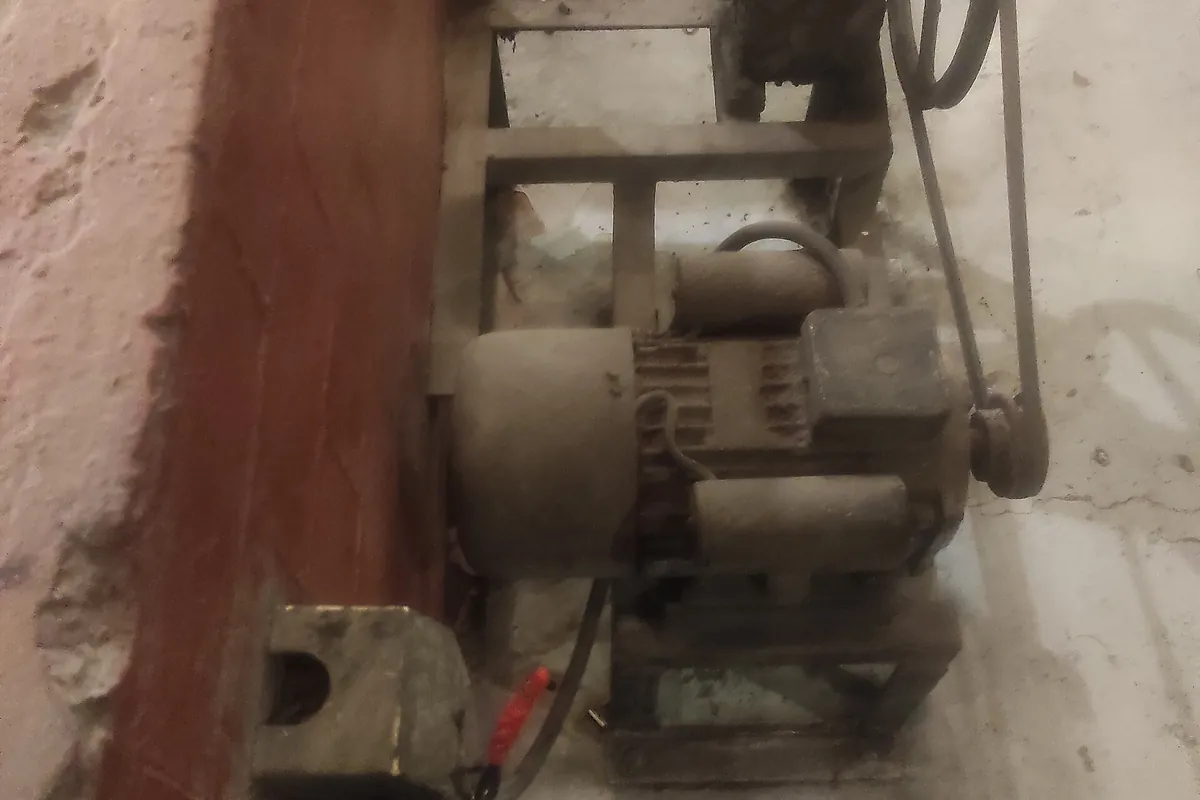
Why megging through a drive destroys drives
An insulation tester puts 500 or 1000 volts DC on the conductor under test. At the drive end those conductors land on output transistors, freewheel diodes, surge suppressors and filter capacitors tied to the chassis, none of which is built to sit at 500 volts DC from an external source. The damage is sometimes immediate and sometimes latent, which is worse, because the drive dies a fortnight later and nobody connects the two events.
The sequence is short and not optional. Lock out, confirm the bus is discharged, then land out the three motor conductors at the drive output along with any output reactor or dV/dt filter, since those hold capacitors to ground as well. At the motor, disconnect thermistors, thermal switches, space heaters and encoder leads first. Afterwards short the tested conductors to ground for as long as the test ran, because a long cable holds its charge. The same discipline is routine in panel and machine wiring.
What the insulation reading should actually be
There is a published number here rather than a rule of thumb. IEEE Std 43, the recommended practice for testing insulation resistance of electric machinery, sets a minimum of 5 megohms, corrected to 40 degrees C, for random wound stator windings rated below 1000 volts at 500 volts DC. That is a floor, not a target. A dry 480 volt motor in service usually reads hundreds of megohms.
Two corrections stop good readings being thrown away. Insulation resistance roughly doubles for every 10 degrees C the winding is colder, so a cold morning reading and one taken after a shift of running are not comparable until corrected. On larger machines the polarization index, the ten minute reading divided by the one minute, says more than the absolute value, and a ratio near 1 means moisture.
Trends beat single readings. A motor that read 900 megohms last year and 40 today is telling you something even though 40 clears the floor. Where the reading is low and the room wet, drying often recovers it, which is information rather than a repair: water is getting in and the next failure is booked. Where the motor will not run at all, our piece on a motor that will not start uses the same readings.
What actually fixes it
If the testing says leakage, the repair is in the wiring method and the parameters, not the motor. Shielded symmetrical VFD cable, bonded 360 degrees at both ends rather than through a pigtail, keeps most of the high frequency current in the cable and returns it to the drive instead of letting it wander through building steel. The grounding conductor runs with the motor leads to the drive chassis.
Carrier frequency is the variable you can change from a keypad in two minutes. Going from 8 kHz to 4 kHz halves the switching edges and often takes a marginal installation back under the threshold, at the cost of audible motor noise. Where the run is too long for that, the NEMA guide has the next step: parasitic capacitance coupling can be cancelled with a reactor or LC filter.
One case catches people out entirely. On an ungrounded or corner grounded delta service, the drive's EMC filter capacitors and surge devices connect to the chassis in a way that is only correct on a solidly grounded wye. Manufacturers fit a removable screw or jumper for exactly this, and left in on the wrong system the drive trips forever. Checking the supply first belongs in electrical preventive maintenance.
- Shielded VFD cable, 360 degree termination at both ends, no pigtails
- Grounding conductor run with the motor leads to the drive chassis
- Carrier down to 4 kHz or 2 kHz before anything gets replaced
- Output reactor or dV/dt filter where the run cannot be shortened
- EMC jumper set correctly on an ungrounded or corner grounded supply
Questions people ask
- Can I just switch the ground fault detection off?
- On most drives there is nothing to switch off, because the threshold is fixed at the factory. Where a parameter exists it protects the output transistors, so raising it turns a nuisance trip into a destroyed drive.
- It trips the instant I press run, before the motor moves. What does that tell me?
- That the residual is there at the first switching edges, which points at the cable or the motor. Test insulation first. A fault that appears only once the drive is at speed is more likely leakage.
- How long is too long for a motor cable?
- Every drive maker publishes a limit, so use theirs. Note that it is often shorter for shielded cable than unshielded, because the shield sits close to the conductors and adds capacitance to ground.
- Would a ground fault relay upstream of the drive help?
- It usually makes things worse. Normal drive leakage is enough to operate conventional residual current devices, so they trip on a healthy installation. Where it is required, the type and setting have to suit the leakage a drive produces.
- The motor reads 3 megohms. Is that a fail?
- It is below the IEEE 43 floor of 5 megohms for a winding rated under 1000 volts, so it does not go back on the drive as it stands. In a washdown room it often recovers after drying, which means finding where water gets in.
Sources worth reading
- IEEE Std 43: Recommended Practice for Testing Insulation Resistance of Electric Machinery
The 5 megohm minimum at 500 volts DC for windings rated under 1000 volts, plus polarization index and temperature correction.
- NEMA: Application Guide for AC Adjustable Speed Drive Systems
Section 5.3.5.7 on ground fault protection: the trip value is fixed by the manufacturer, and parasitic capacitance from long or wet cables is listed as a cause.
What we do about it
Who wrote this
We commission drives on farm and plant equipment across Lebanon, Lancaster and Berks counties, and we get called to the ones that will not stay running. If a drive is faulting on ground fault while the motor tests clean, the answer is usually in the cable and the carrier setting rather than in the box.
Slon Electric is a family run electrical contractor in Myerstown, Lebanon County. Anatoly runs the crew and usually answers the phone himself. We work on farms, in plants and in commercial buildings across Lebanon, Lancaster and Berks counties, we are rated 5.0 on Google, and the phone is covered around the clock.