
What does a variable frequency drive actually do, and do I need one?
What a variable frequency drive does, when it pays and when it does not
Short answer
A VFD rectifies incoming AC to DC, then switches that DC back into AC at whatever frequency you ask for, using pulse width modulation. Because an induction motor's speed follows the frequency it is fed, one motor can run anywhere from a crawl to above nameplate speed. On a fan or a centrifugal pump that pays for itself, because input power varies with the cube of speed: the Department of Energy puts a 20 percent cut in speed at roughly a 50 percent cut in input power. On a conveyor, or anything needing full torque at every speed, a drive buys control but almost no energy, and a soft starter is often cheaper.
Most VFD questions are really two questions. What does the thing do, and will it pay for itself on this particular load. The first has a clean answer. The second depends almost entirely on whether the load is centrifugal, and that is the part people skip.
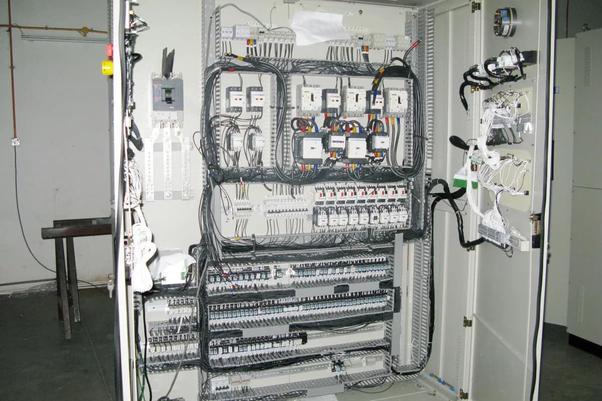
What is actually happening inside the box
Three stages, in order. A diode bridge rectifies incoming three phase AC into DC. A bank of capacitors holds that DC bus steady at about 1.35 times the line voltage, so roughly 650 volts DC on a 480 volt supply. Then six IGBT transistors switch that bus on and off to build a new AC waveform.
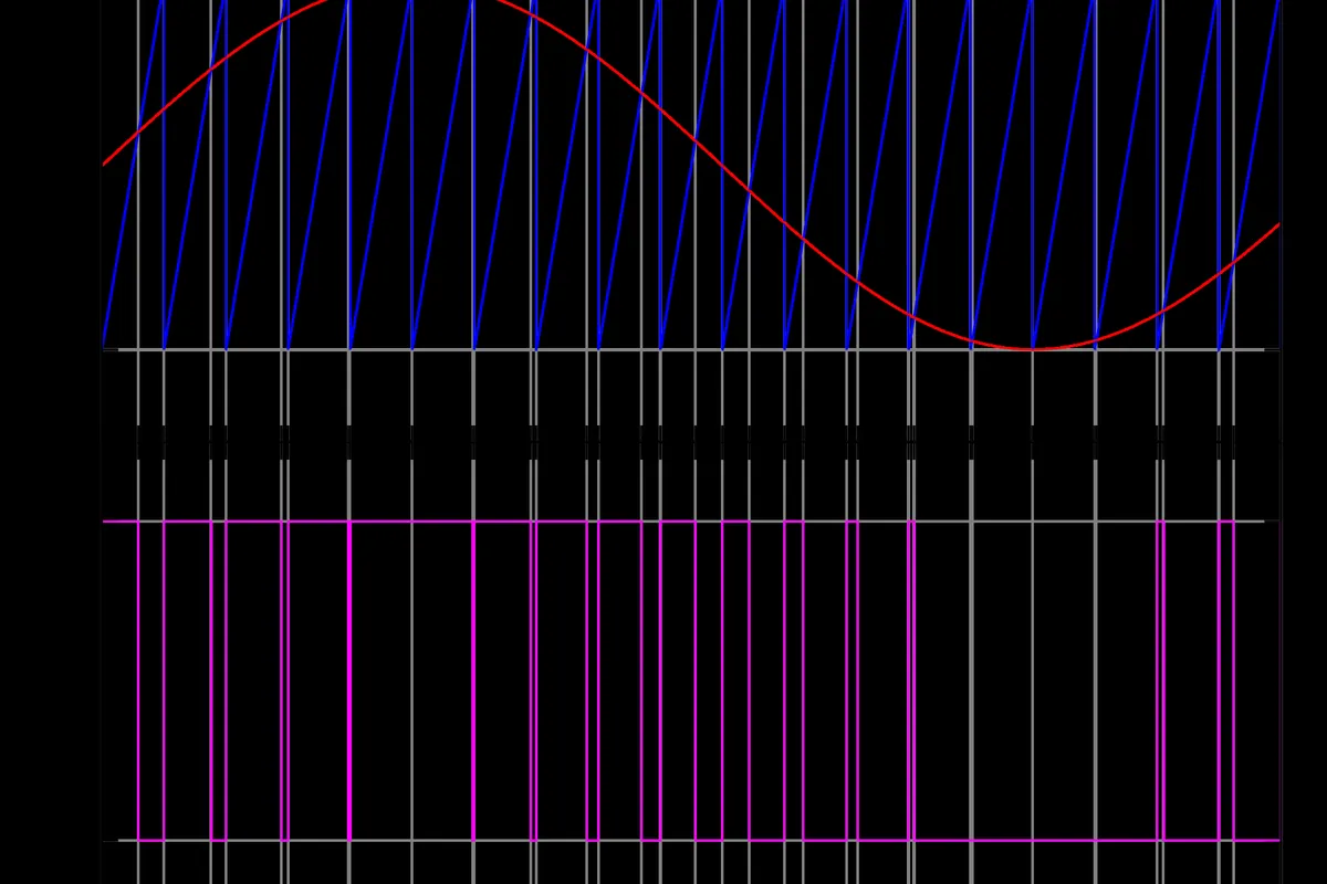
That last stage is the pulse width modulation. The transistors switch at a carrier frequency, typically 2 to 16 kHz, and each pulse is widened or narrowed so the average voltage over an output cycle traces a sine wave. The motor windings are inductive and smooth that pulse train into near sinusoidal current. The voltage at the motor terminals never is a sine wave, and that matters later.
Speed then follows frequency. Synchronous speed is 120 times frequency divided by poles, so a four pole motor is 1800 rpm at 60 Hz and 900 rpm at 30 Hz. Below base speed the drive holds volts per hertz constant to keep flux right, about 7.7 volts per hertz on a 460 volt motor. Above base speed it cannot raise voltage further, so torque falls away.
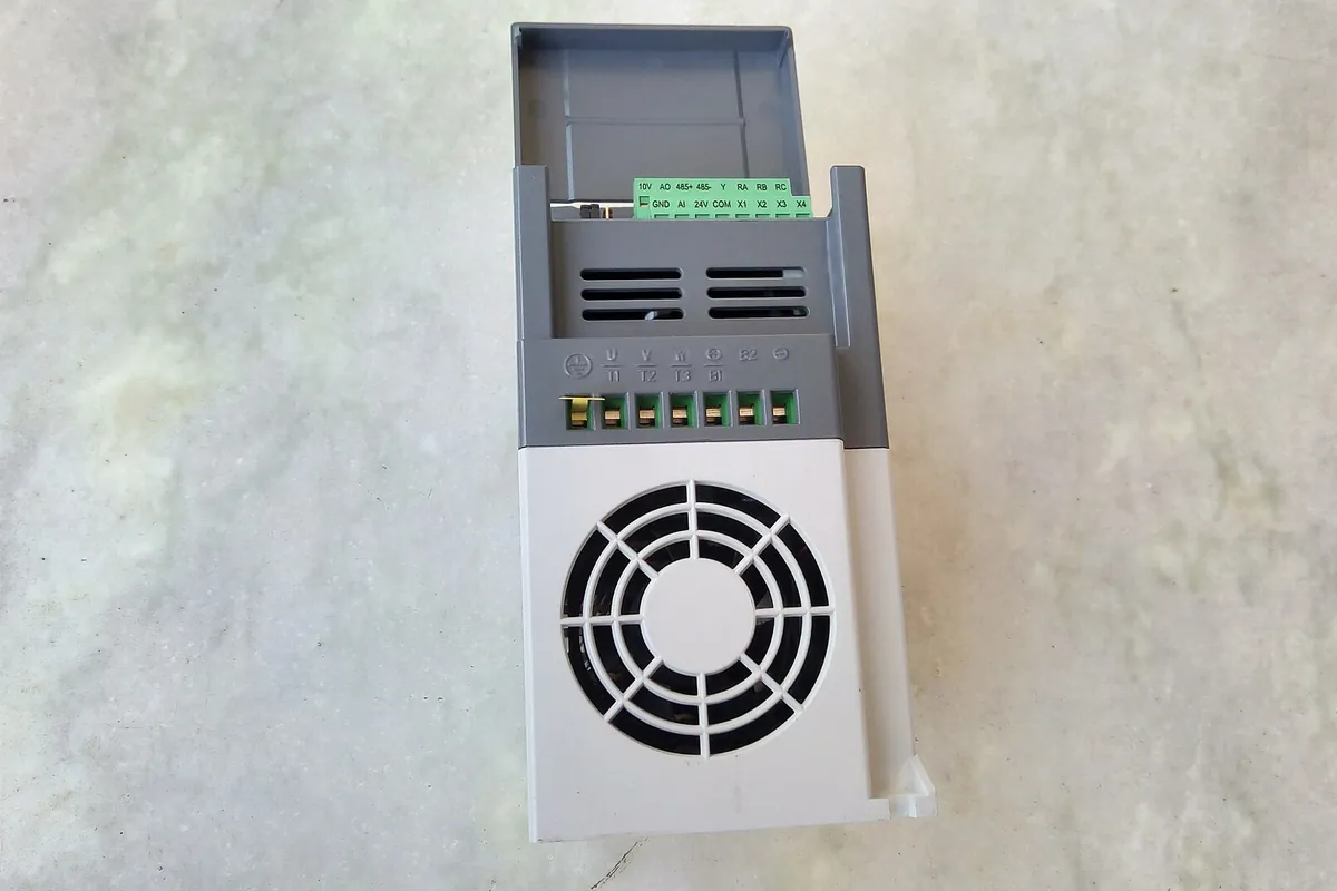
Why a fan at 80 percent costs half the power
For centrifugal fans and pumps the affinity laws govern everything. Flow varies with speed, pressure with the square of speed, and input power with the cube. That third relationship is the whole economic case.
Work it through on a 20 horsepower tunnel fan. At full speed it takes 20 hp at the shaft. At 80 percent speed, 0.8 cubed is 0.512, so the shaft load drops to about 10.2 hp. At 60 percent it is 4.3 hp, and at half speed 2.5 hp. The Department of Energy tip sheet on adjustable speed drive part load efficiency states the same thing: cutting speed or flow by 20 percent cuts input power by roughly 50 percent.
Throttling a pump with a valve or damping a fan does not reduce the work much, it moves the operating point up the curve and burns the difference across the restriction. Two warnings, though. The cube law assumes no static head, so a pump lifting water a real distance saves less and needs its own system curve. And a fan that runs flat out anyway has nothing to save. Ventilation pays best because those fans genuinely modulate, as in the poultry house ventilation power job.
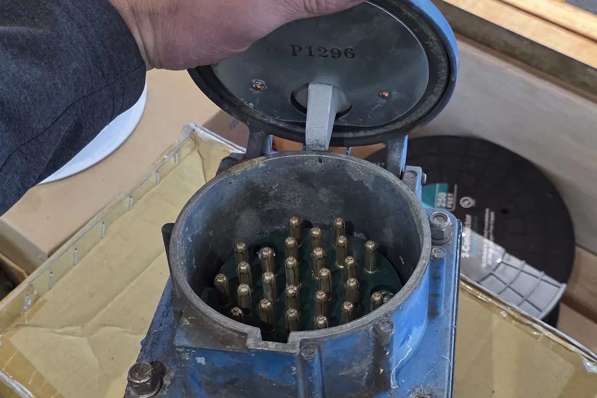
When a VFD is the wrong answer
Constant torque loads do not follow the cube law. Conveyors, augers, hoists, mixers, positive displacement pumps and reciprocating compressors need roughly the same torque at every speed, so power falls only linearly. Worse, a fan cooled motor loses its own cooling as it slows, so running one at 20 Hz for long periods needs a blower kit or an oversized motor.
If all you want is a gentler start, a soft starter does that for less money, in less panel space, with no harmonics and no reflected wave problem. If the load runs at one speed ninety five percent of the time, a drive is control you are not using.
One more case against. A bank of six pulse drives puts real harmonic current onto a service, and on one that is already tight that means transformer noise and nuisance tripping elsewhere. It is a load study question before it is a drive question, and it belongs in the control panel and machine wiring conversation early.
- Constant torque loads: conveyors, augers, positive displacement pumps
- Soft start only, where a soft starter is cheaper and simpler
- One speed almost all the time, so the speed control never earns anything
- A standard motor on 480 volts with a long lead, which often does not survive
- Several drives on a service with no headroom for their harmonic current
What kills drives and motors in the field
Start with the cable. Use shielded VFD cable, three symmetrical conductors with a ground, terminated 360 degrees at both ends, not loose conductors sharing conduit with control wiring. The switching edges radiate, and unshielded output leads beside a sensor cable give signal faults that look like an instrument problem for weeks.
Then cable length. The NEMA application guide for AC adjustable speed drive systems sets out the mechanism: cable and motor behave as a resonant circuit, and every switching edge rings. With modern IGBT drives the overshoot reaches twice the DC bus voltage at under 50 feet of lead, and beyond about 400 feet it can ring higher still. MG1 Part 31 inverter duty motors take repetitive peaks of 3.1 times rated rms, about 1430 volts on a 460 volt motor, while a general purpose motor under Part 30 is rated for 1000 volts. The fix is a load reactor or dV/dt filter, a lower carrier frequency, or an inverter duty motor.
Third, bearings. Common mode voltage on the shaft discharges through the bearing and pits the race, and the pitting becomes the washboard pattern called fluting, audible long before it seizes. NEMA lists the countermeasures: a shaft grounding brush or ring, insulated bearings, a lower carrier frequency, a common mode filter, and grounding drive and motor exactly as the maker says. On any motor you cannot afford to lose, a grounding ring is cheap insurance, and that detail is routine on the industrial work we do.
When it trips on ground fault
The first thing to understand is that you cannot check a drive's output with an ordinary meter. The output is a pulse train at the carrier frequency, not a sine wave, so an average responding meter is meaningless on it, and even a true RMS meter reads switching content along with the fundamental. Trust the drive's own display for output voltage and current, and do insulation testing at the motor with the drive disconnected.
The second is sensitivity. A drive detects a ground fault by summing its three output currents and looking for the difference, and many ship with that threshold around 5 percent of rated output current. That is far more sensitive than the breaker feeding it, so a drive trips on leakage nothing upstream notices: cable capacitance, a washed down motor, a damp junction box. Working in order saves guessing, and it is the order we use commissioning machine and motor control connections.
Ground fault trip: the order to work in
- 1. Note when it trips: on power up, on start, at one speed, or at random under load. Each points somewhere different.
- 2. Open the disconnect and lock out. Confirm the DC bus has discharged, because it sits at several hundred volts for minutes.
- 3. Disconnect the three motor leads at the drive output and megger motor and cable together, phase to ground, at 500 volts DC. Never megger through a drive.
- 4. If that reads low, split it and test motor and cable separately. Below 1 megohm on either is the fault. A washed down motor often recovers after drying, which tells you where water gets in.
- 5. If both are clean, look at the run. Long unshielded leads have enough capacitance to earth to trip a drive at its factory setting on their own.
- 6. Drop the carrier from 8 kHz to 2 or 4 kHz. Less switching means less capacitive leakage, and it often stops nuisance trips outright, at the cost of audible noise.
- 7. Check the grounding. The equipment grounding conductor must run with the motor leads back to the drive chassis, not to the nearest building steel.
- 8. Only then suspect the output transistors. With the drive dead, diode test from each output terminal to both bus rails and compare the three phases.
Using a drive instead of a phase converter
A drive will run a three phase motor from a single phase supply, and for one machine on a farm or in a shop it is usually the cheapest way to do it. The rectifier does not mind that only two of its legs are fed. What changes is the stress on the bus.
The rules are short. Use a drive its maker rates for single phase input, or derate a three phase drive, with roughly half of nameplate the usual guidance, so a 10 hp drive runs a 5 hp motor. Add an input line reactor, because bus ripple current roughly doubles and the capacitors are what wear out.
The limits matter more than the trick. One drive runs one motor. You cannot take three phase off the output to feed a panel, a starter, a control transformer or a welder. If several machines need three phase, the honest answers are a rotary converter or utility service, which we compare in the three phase write up.
Questions people ask
- Will a drive save money on my augers and conveyors?
- Very little. Those are constant torque loads, so power falls in line with speed rather than with its cube. A drive on a conveyor is bought for process control or gentle starting, and energy saving should not be in the business case.
- Can I use the motor I already have?
- Often yes at 230 volts and short leads, often no at 460 volts with a long run. What decides it is whether peak voltage at the motor terminals stays under what that insulation is rated for. Measure the lead length first, then choose between a reactor, a filter and a new motor.
- My meter reads a strange voltage on the drive output. Is the drive faulty?
- Probably not. The output is a switched pulse train, not a sine wave, so a handheld meter has nothing sensible to average. Read output voltage and current from the drive's display, and use the meter on the input side where the waveform is real.
- Can I put a disconnect between the drive and the motor?
- Yes, and for a motor out of sight of the drive you need one anyway. What you must not do is open it while the drive is running, because that produces an arc the output stage will not survive. Use an auxiliary contact to stop the drive before the poles part.
- How long should a drive last?
- Ten to fifteen years in a clean, cool panel, and much less in a dusty one or above rated ambient. The bus capacitors dry out and the cooling fans clog, so both are wear items. Blowing out the heatsink at every service visit adds years for almost nothing.
Sources worth reading
- US Department of Energy: Adjustable Speed Drive Part-Load Efficiency, Motor Systems Tip Sheet 11
The affinity law relationship and the 20 percent speed to 50 percent power figure, from the source.
- NEMA: Application Guide for AC Adjustable Speed Drive Systems
Cable length and reflected wave, MG1 Part 30 and Part 31 voltage limits, shaft voltage and bearing currents.
What we do about it
Read next
Who wrote this
We build and wire the panels these drives live in, connect them to the machine, and get the call when one starts tripping at three in the morning. If you are weighing a drive against a soft starter, or you have one that will not stay running, the useful conversation starts with the load and the cable.
Slon Electric is a family run electrical contractor in Myerstown, Lebanon County. Anatoly runs the crew and usually answers the phone himself. We work on farms, in plants and in commercial buildings across Lebanon, Lancaster and Berks counties, we are rated 5.0 on Google, and the phone is covered around the clock.