
Machine connection and the motor control behind it
Lebanon County, PA
Connecting a new machine is where the machine builder's world and the plant's world have to meet, and the documentation almost never covers the join. The electrical side decides whether the machine starts reliably, whether it protects its own motors, and whether anyone can troubleshoot it five years from now.
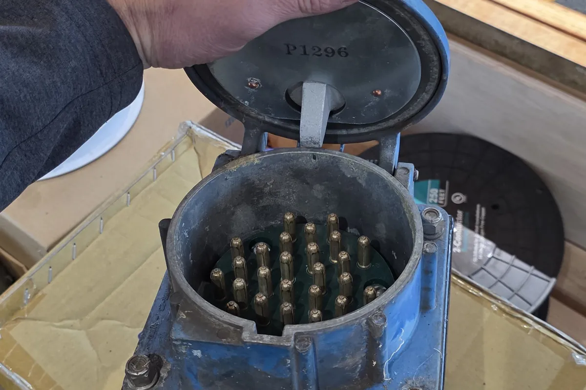
What the machine documentation gives you, and what it leaves out
Most machines arrive with a drawing set, and the first job is to read it rather than assume it. Packages written for a family of machines often describe options that were not ordered, and imported equipment frequently shows 400V at 50Hz and component references that do not exist here. None of that is a problem if it is caught before the disconnect is mounted.
What is usually missing is the plant side of the connection. The drawings show the machine panel and stop at its terminals. They rarely state the point of connection, the disconnecting means, the branch circuit protection or how the machine is meant to talk to anything else in the building.
Two numbers on the machine nameplate matter more than the rest. Full load current sets the supply conductors and the maximum overcurrent device, and the short circuit current rating decides whether the machine can legally sit where it is going. A panel rated at 5kA cannot go on a service with far more available fault current than that, and it is the item most often found after the equipment is already on the floor. Article 670 of the National Electrical Code covers industrial machinery and is worth reading alongside the builder package.
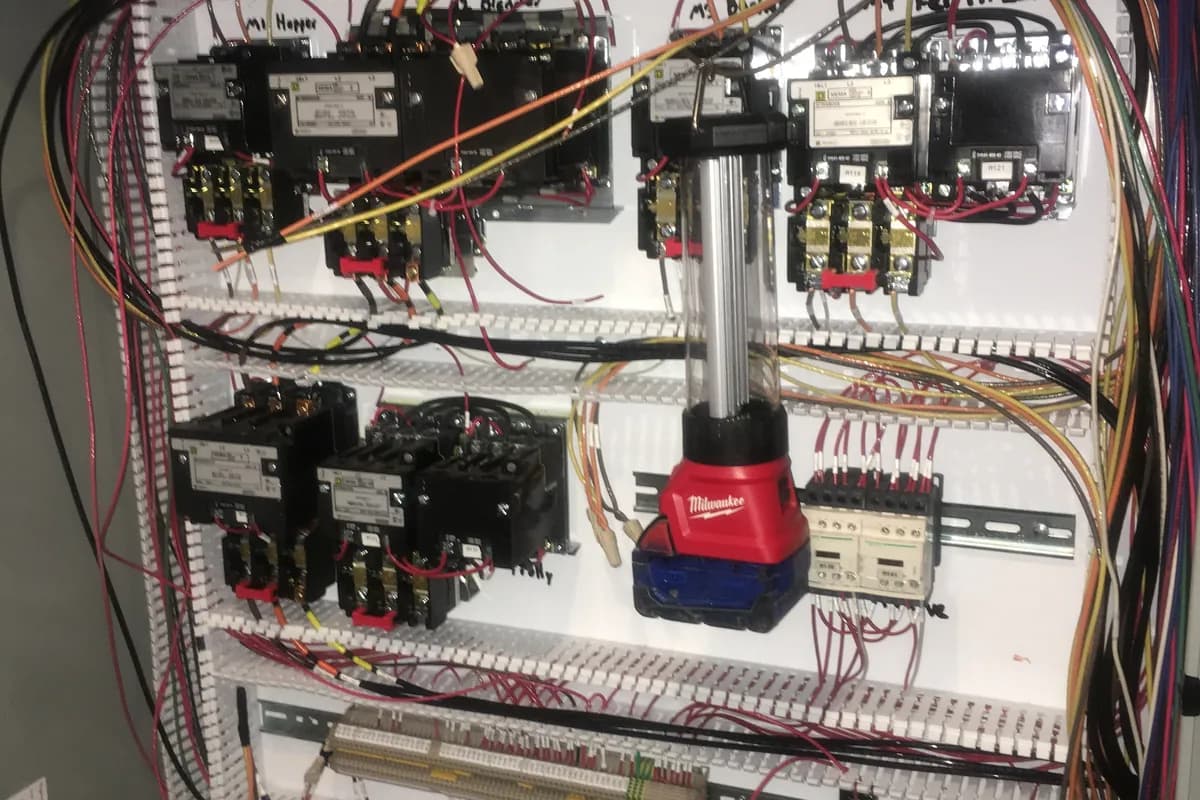
Choosing what actually starts the motor
Across the line starting is still the right answer for a great many motors. It is simple, cheap and nothing sits between the contactor and the windings to fail. The cost is inrush. A standard induction motor started direct on line typically draws around six to eight times its full load current for the first moments, and on a soft feeder or a generator that shows up as a visible voltage dip on everything nearby.
A soft starter solves inrush and nothing else. It is the right tool where the mechanical load does not like a hard start, conveyors and pumps in particular, and where nobody needs speed control afterwards.
A variable frequency drive earns its place when the process wants speed, torque control or real energy savings on a variable torque load such as a fan or centrifugal pump. It is not a free upgrade. A drive adds heat, a set of parameters and a component that eventually fails, and it changes the wiring rules around it. Where several motors sit together, grouping the starters and drives into one lineup usually beats scattering them, which is the thinking behind our control panels and machine wiring.
Overload protection belongs to the nameplate
The most common fault we find on other people's machine connections is overload protection set from the wrong number. The breaker or fuse ahead of a motor circuit protects the conductors and clears a short circuit. It is not motor protection, and it is sized well above running current precisely so it does not trip on starting. The overload relay is what protects the motor.
Article 430 sets the method. Overload protection is generally sized at 115 or 125 percent of nameplate full load amps depending on service factor and temperature rise, and the nameplate means the motor in front of you rather than a horsepower table. Replacement motors are the usual trap, because a rewound or substituted motor often draws a different full load current than the one it replaced.
- Set overloads from the motor nameplate, not from the breaker or the horsepower table
- Check service factor, ambient temperature and altitude before accepting a default setting
- Re-check the setting whenever a motor is replaced or rewound
- Confirm the machine short circuit current rating against available fault current at the point of connection
- Record the final settings somewhere the plant can find them again
Drives, cable and grounding
A drive output is not a sine wave. It is a fast switching pulse train, and it behaves like a radio transmitter connected to a few hundred feet of wire. That is why drive output cable is a specified item rather than whatever is on the van. Symmetrical grounding conductors and a proper shield, bonded three hundred and sixty degrees at both ends, keep the return current where it belongs instead of through building steel.
Lead length has a hard limit set by the drive manufacturer. Beyond it, reflected wave effects can nearly double the voltage seen at the motor terminals, and the winding insulation is what pays. Output reactors and filters exist for that reason. On larger motors, shaft grounding rings or insulated bearings deal with circulating currents that otherwise pit the bearing races and cause a failure that looks mechanical but is not.
Separation is the other rule. Drive output cable does not share a raceway or a tray with control or instrument wiring. Running a signal pair alongside a drive output is the fastest way to turn a good transmitter into an unstable reading, as covered in instrument racks and process signal wiring.
Safety circuits and e stops
An emergency stop is not a button wired into a coil. NFPA 79 describes stop categories, and the difference matters: category zero removes power immediately, category one brings the machine to a controlled stop and then removes power. Which one a machine needs depends on what it does when it loses power suddenly, and on what the builder specified.
The circuit behind the button carries the same weight. Dual channel monitored inputs into a safety relay or a safety rated controller exist so that one broken wire or one welded contact does not quietly remove the protection. Guard interlocks belong in the same circuit and should not be defeatable with a spare key left on the panel.
Restart behaviour is the part that gets missed. After an emergency stop or a loss of supply, a machine should require a deliberate restart rather than starting on its own when power returns. This matters twice over during an outage, when equipment is repeatedly de energised and re energised, as described in plant wiring inside a shutdown window.
Labelling for the person who comes next
A machine connection is finished when someone who has never seen it can troubleshoot it at three in the morning. That means wire numbers on both ends matching the drawings, printed terminal markers rather than handwriting, a correct panel schedule and a drawing set that reflects what was actually built.
The same applies outside the panel: the disconnect identified with what it feeds, the source marked on the machine, arc flash labelling current for the equipment, and field devices tagged to match the drawings. None of it takes long during installation and all of it is expensive to reconstruct later.
This work sits alongside the rest of our industrial electrical services and turns up in every plant we deal with, from packaging lines to the washdown rooms described in food plant equipment power. Machines documented properly at connection are also the ones that stay cheap to keep running under a preventive maintenance program.
Services used on this job
Got something like this coming up?
Tell us what the building is and what it has to run. We will tell you what it needs and what it takes. The phone is answered around the clock.