
Instrument racks and process signal wiring
Berks County, PA
Process signal wiring looks like small wire, which is exactly why it gets treated carelessly. A 4 to 20 mA loop carries the number a plant runs on, and it is far more sensitive to what is installed beside it than any power circuit will ever be. Instrument work is a separate discipline from power work and repays being treated as one.
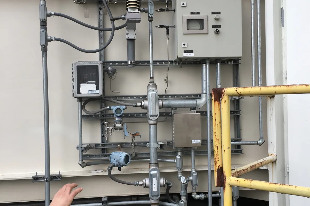
Power and signal are two different jobs
A power circuit has one obligation: deliver current without overheating or tripping. A signal circuit has to deliver a number that is still correct after travelling a few hundred feet through a building full of motors, contactors and drives. Article 725 governs the class two and class three circuits most instrumentation falls under, and it starts by keeping them out of the raceways and enclosures used by power conductors.
The practical rule is separation by distance and by geometry. Signal runs get their own conduit or their own tray section, not spare space in a power raceway. Where a crossing is unavoidable it happens at a right angle, because parallel runs couple and perpendicular ones largely do not. Where a parallel run cannot be avoided, distance and a steel raceway do most of the work.
The other half of the discipline is intent. A power circuit gets installed once and then ignored. A signal circuit gets calibrated, verified and troubleshot repeatedly, so it has to be built to be taken apart. That is why we treat instrument work as its own scope within our industrial electrical services rather than as small wire pulled by whoever is free.
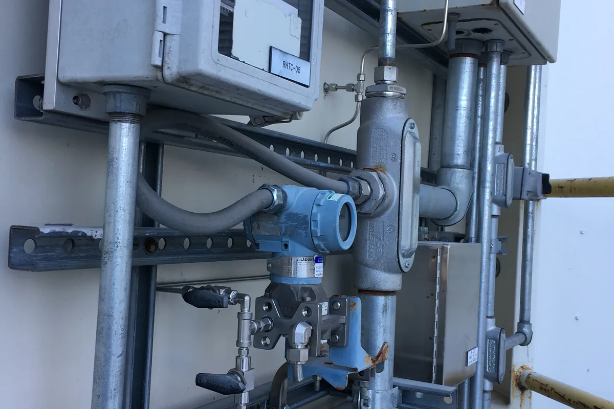
Shield, drain and single point grounding
Instrument cable is twisted for one reason and shielded for another. Twisting means whatever noise couples into the pair couples into both conductors roughly equally, so the receiving instrument rejects it. The shield catches what the twist does not, and the drain wire gives that captured energy a way out.
Where the drain lands is the decision people get wrong. For a low frequency analogue loop, ground the shield at one end only, normally at the panel or rack where the loop is powered, and leave it cut back and insulated at the field end. Grounding both ends connects two points in a building that are almost never at the same potential, and the current that then flows down the shield is the noise you were trying to avoid.
That rule has exceptions and they come from the device manufacturer, not from habit. Some high frequency network and encoder cables are specified for three hundred and sixty degree bonding at both ends, and the instruction sheet wins. What does not vary is that every shield lands on a dedicated shield bar in the rack rather than on whatever screw is nearest.
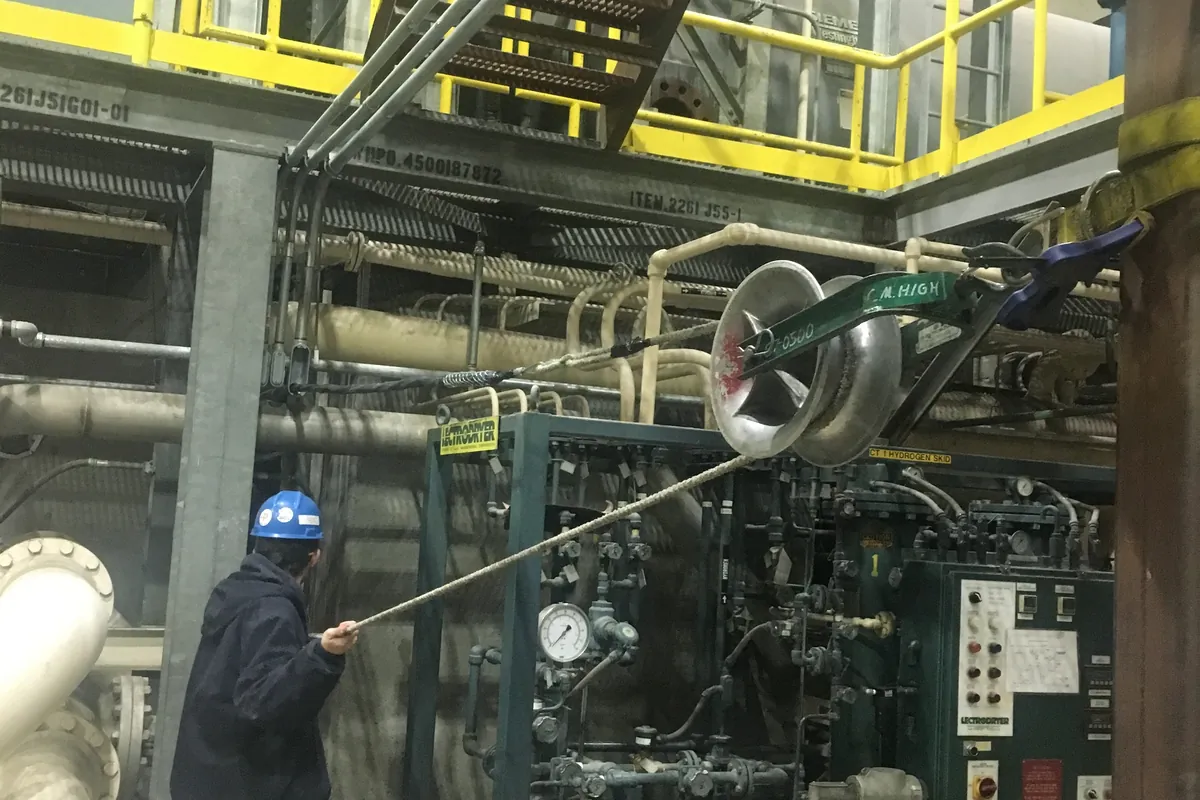
What a drive does to a signal pair beside it
A variable frequency drive output is a fast switching waveform, and its rise times put energy at frequencies that couple easily into anything running alongside. A signal pair in the same tray as a drive output does not fail cleanly. It produces a reading that drifts, jumps when the drive accelerates, or sits a few percent off in a way nobody notices until a batch goes wrong.
The symptom that gives it away is correlation. If a transmitter misbehaves only when a particular motor is running or ramping, the cause is coupling rather than the instrument. Chasing that with a replacement transmitter wastes a day and a part.
Prevention costs nothing at installation and a great deal afterwards. Drive output cable stays in its own raceway, is the correct symmetrical grounded type and is bonded properly at both ends, which is covered in the machine connection and motor control work. Signal runs keep their distance, cross at right angles, and stay out of panels where drives are mounted unless there is a physical barrier between them.
The 4 to 20 mA loop and where it fails
The loop standard has survived decades because it is hard to break in a subtle way. Current is the same everywhere in a series loop, so voltage drop over a long run does not change the reading, and the live zero at 4 mA means a broken wire reads as a fault rather than as a legitimate zero.
Where loops do fail is in the supply and the burden. A two wire transmitter needs a minimum voltage at its terminals, and everything in the loop, the wiring, the controller input, any indicator added later, takes a share of it. Add one device to a loop already near its limit and the reading stops tracking at the top of the range while looking fine at the bottom.
- Add up the loop burden before adding an indicator, recorder or isolator to an existing loop
- Moisture in a field junction box shows up as a low reading or a slow drift, not as a clean failure
- Two supplies on one loop, usually from a well meant addition, produce readings nobody can explain
- Shields grounded at both ends give noise that tracks nearby equipment starting and stopping
- Where the process is flammable, intrinsically safe loops need their own barriers, separation and cable identification
Terminating at the rack so calibration is possible
A rack is not finished when the wires are landed. It is finished when a technician can verify a loop without taking anything apart. That means knife blade or disconnect terminal blocks so a loop can be broken and a calibrator inserted in series, fused terminals where the design calls for them, and enough slack to pull a device forward and work on it.
Layout follows the same logic. Alternating current and direct current terminals go on separate strips with a gap between them, loop numbers are printed on markers that match the loop sheets, and spare pairs are landed and labelled rather than coiled in the bottom of the enclosure. Outdoor racks need enclosure ratings, sun shading and breathers appropriate to standing outside through a Pennsylvania winter.
Documentation is the deliverable that matters most here. A loop sheet showing every terminal a signal passes through, from transmitter to rack to controller input, is what turns a two hour troubleshooting call into a ten minute one. Our control panels and machine wiring work is built to the same standard for the same reason.
Where instrumentation meets controls and low voltage
Instrument wiring does not stop at the rack. It lands in a controller, and from there it becomes network cable, remote input and output stations and whatever the plant uses for supervision and historical data. The physical standards for those runs sit on the low voltage and structured wiring side of the business, and the same rules about separation, bonding and labelling apply.
The field side connects to the rest of the plant as well. Process instrumentation in a washdown area carries all the enclosure and routing constraints described in food plant equipment power, on top of everything above. Loop verification is also one of the longest items on any restart checklist, which is why it gets planned early in the kind of outage described in plant wiring inside a shutdown window.
The common thread across all of it is that signal work rewards discipline at installation and punishes shortcuts for years. A pair run in the wrong raceway is invisible on the day and expensive every time the plant chases a reading that nobody trusts.
Services used on this job
Got something like this coming up?
Tell us what the building is and what it has to run. We will tell you what it needs and what it takes. The phone is answered around the clock.