
The motor hums but will not turn, or it trips the overload on every start. Where do I begin?
A three phase motor that hums, will not turn, or trips the overload: the order to check
Short answer
Start by deciding whether the fault is electrical or mechanical, because that takes two minutes and rules out half of everything. Lock out and turn the shaft by hand: if it will not turn, the problem is the load or the bearings, not the supply. If it turns freely and the motor still hums without starting, the usual cause is single phasing, one leg open at a fuse, a contactor pole or a broken conductor. A motor that loses a leg while already running will keep turning under light load and quietly cook itself, so the reading that matters is line current and voltage taken at the motor while it is trying to work, not at rest.
Most motors that will not start are not faulty motors. They are a blown fuse, a burnt contactor pole, a loose connection that reads fine at rest, or a load that has seized over the weekend. The trouble is that all of those produce the same complaint, so the only reliable way through is a fixed order of checks that each rule something out.
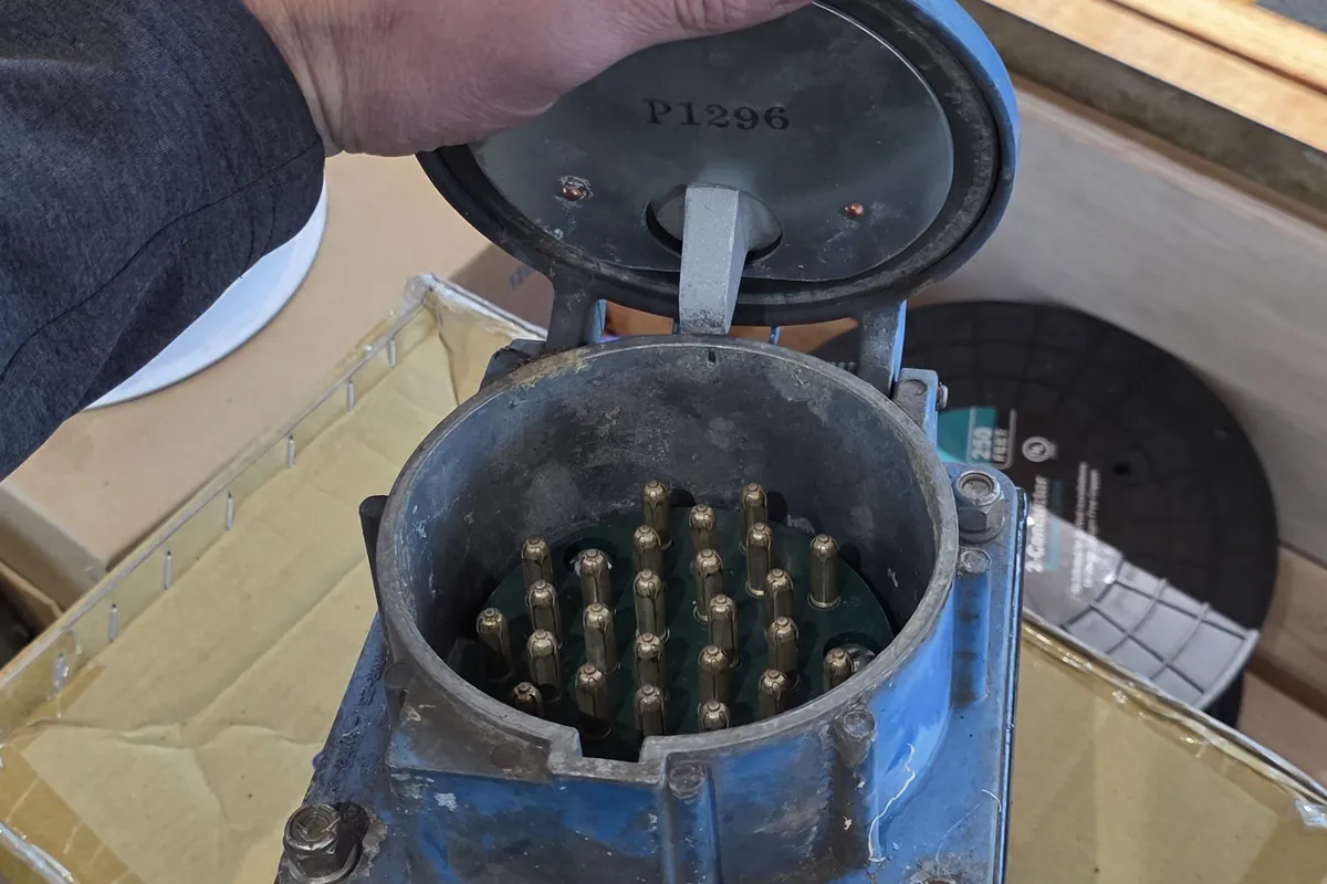
Mechanical or electrical, in the first two minutes
Lock out, then put a hand or a wrench on the shaft and turn it. A healthy motor with a free load turns with modest effort. If it will not move, or it grinds, you have found the fault and no meter will help: a seized bearing, a jammed conveyor, a brake that has not released, a pump packed with product that set overnight.
This matters because a motor that cannot turn behaves exactly like a motor that has lost a phase. Both hum, neither accelerates, and both draw locked rotor current, typically six to eight times full load amps, until the overload catches it. Deciding between them first stops an afternoon of electrical fault finding on a mechanical problem, and it is the first question on any industrial service call.
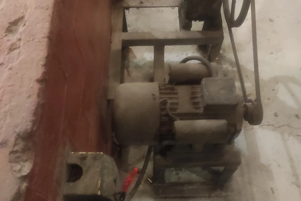
Single phasing, and why it is the usual answer
Lose one of three legs and the motor cannot produce a rotating field, so from rest it sits and hums. Already running, it is a different story: the rotor keeps it turning, the machine sounds normal, and under light load nothing looks wrong. Current in the two surviving legs rises by roughly 1.73 times for the same shaft load, and the winding heats until something gives.
The usual causes are ordinary: one open fuse, a pitted or welded contactor pole, a broken conductor at a junction box, or an open primary on the utility side that takes out a whole yard. Protection is meant to catch this, which is why the code requires an overload device in every ungrounded conductor rather than one in a single leg. The IAEI walk through of motors and motor circuit protection is clear on the distinction that gets missed here: overload protection is not short circuit protection, and the two are sized from different rules.
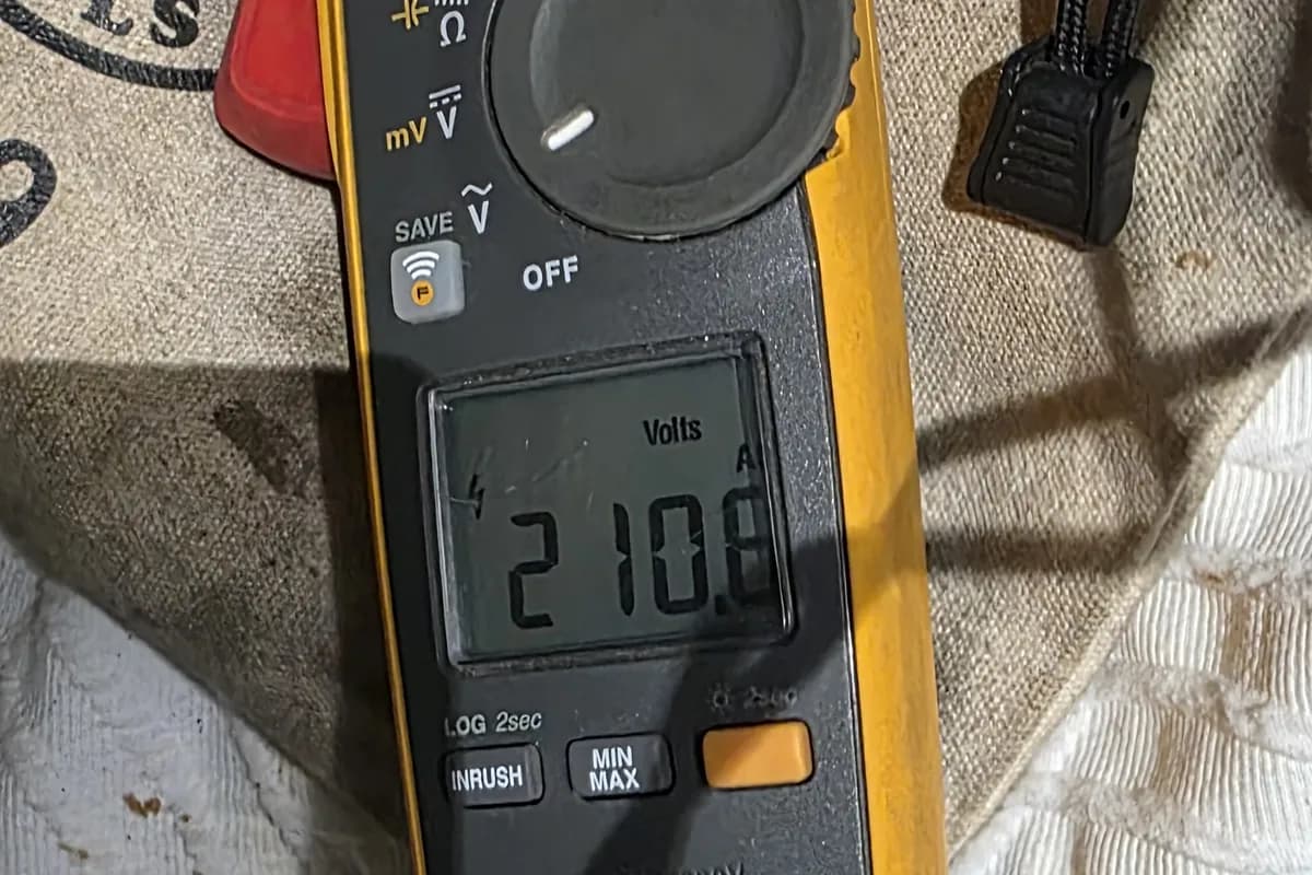
Measure under load, not at rest
A voltage reading taken with the motor stopped proves almost nothing. A high resistance joint, a corroded fuse clip or a contact that has lost its face still shows close to source voltage with no current flowing, because the meter draws nothing. Put 40 amps through that joint and the voltage collapses across it. An open leg also reads voltage back through the motor windings from the other two phases, which is why a leg can look alive and be dead.
So the useful readings come during a start attempt or with the machine loaded: three line to line voltages at the motor terminals, three line currents, and the nameplate to compare them against. The order below is what we work through on plant and farm equipment, including the motor circuits in grain handling power and controls.
No start diagnosis: what each reading rules in or out
- 1. Lock out and turn the shaft by hand. Free means electrical, stiff or seized means mechanical and you are done here.
- 2. Check fuses and the breaker, then measure line to line at the starter line terminals: three readings within a few volts, say 480, 479 and 478. One leg low or missing is a supply problem ahead of the starter.
- 3. Attempt a start with a clamp on each leg. Locked rotor current, six to eight times full load amps, on two legs and nothing on the third is single phasing. Equal locked rotor current on all three points at the load.
- 4. Measure line to line at the motor terminals during that attempt. A leg that sits at 480 at rest and falls to 390 under starting current is a high resistance connection between there and the source.
- 5. With the machine running at normal load, take all three voltages again and calculate unbalance. Anything over 1 percent gets investigated before anything is replaced.
- 6. Take the three line currents at the same time. They should sit within about 10 percent of each other and below nameplate full load amps. One leg well high on balanced voltage points inside the motor.
- 7. Lock out again and measure winding resistance between each pair of leads. Three readings within about 5 percent, say 0.62, 0.63 and 0.61 ohms, clear the windings. One high reading is an open or a bad internal joint.
- 8. Megger the windings to ground at 500 volts DC. Hundreds of megohms is normal, the IEEE 43 floor for a winding under 1000 volts is 5 megohms, and below 1 megohm the motor comes out.
- 9. Last, check the overload is set for this motor. Heaters and dial settings get changed during a previous callout and never changed back.
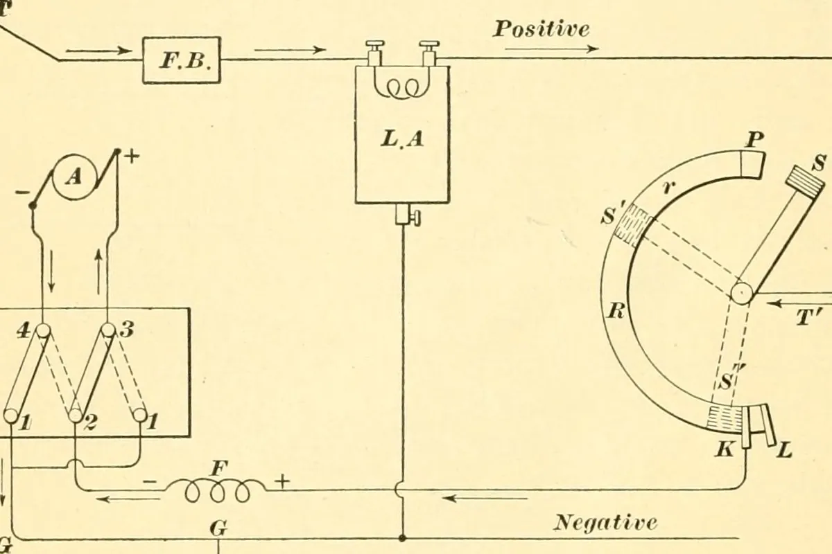
Voltage unbalance does more damage than the number suggests
Percent voltage unbalance is the largest deviation from the average divided by the average. The Department of Energy tip sheet on eliminating voltage unbalance works the example: measured line voltages of 462, 463 and 455 volts average 460, the largest deviation is 5 volts, so the unbalance is 1.1 percent. That is a reading most people would walk past.
It should not be. Current unbalance runs several times higher than voltage unbalance, commonly six to ten times, so 1 percent on the voltmeter can mean 8 percent on the clamp and a winding hot enough to lose years of life. DOE recommends keeping unbalance at the motor terminals under 1 percent, and NEMA MG 1 requires derating above that: roughly 0.95 of rated horsepower at 2 percent, 0.88 at 3 percent and 0.75 at 5 percent. Most manufacturers void the warranty past 1 percent as well.
The causes are all fixable: single phase loads piled unevenly on one phase of the service, a transformer bank too small for the three phase load on it, power factor correction equipment misbehaving, an unidentified phase to ground fault, or a loose connection on one leg. Finding that last one is what thermal scanning is for, as in the infrared survey of a switchboard.
Starter, overloads and windings
Open the starter and look before measuring. Contactor faces pit and weld, coils fail, and one pole often looks visibly worse than the other two, which is the single phasing cause sitting in plain sight. Overload relays have to match the motor: the code sizes them from nameplate full load current, 125 percent for a motor marked with a 1.15 service factor or a 40 degree C rise, and 115 percent for everything else. A relay left set for the motor that was replaced two years ago either trips constantly or protects nothing.
One belief costs more motors than any other. Most three phase industrial motors have no internal thermal protection at all, so people hunt for a reset button that does not exist and eventually decide the motor is fine. Unless the nameplate says thermally protected, the only thing standing between that winding and a burnout is the overload relay in the starter.
Windings are the last thing to suspect, not the first. Resistance between each pair of leads should sit within about 5 percent, and insulation to ground far above the IEEE 43 floor of 5 megohms. If the motor runs from a drive rather than a starter, the fault finding changes shape, and drives that trip on ground fault covers that path.
- Visible pitting or welding on one contactor pole, the commonest single phasing cause
- Overload heater or dial matched to this motor nameplate, not the last one
- Winding resistance within about 5 percent across the three pairs
- Insulation to ground in the hundreds of megohms, not single figures
- No assumption of built in thermal protection unless the nameplate says so
When it only fails on hot days or under load
A motor that starts every morning in April and refuses in August, or starts unloaded and stalls loaded, is usually telling you about the feeder rather than itself. Torque falls with the square of applied voltage, so a motor seeing 10 percent low voltage at its terminals makes only about 81 percent of its rated starting torque. Add a hot day, a long aluminium run that has warmed up, and a denser load, and it stops being enough.
That is a voltage drop calculation, not a motor repair. Long runs to a barn, a shop or an irrigation pump are the usual offenders, and the code's informational notes point at 3 percent on the branch circuit and 5 percent overall as the practical limit. We work through a real example, conductor size, distance and result, in the voltage drop write up.
Questions people ask
- Is there a reset button on the motor itself?
- Almost never on a three phase industrial motor. Internal thermal protection is common on small single phase motors and rare above a few horsepower, so unless the nameplate says thermally protected, the reset you want is on the overload relay in the starter.
- It runs fine empty but trips as soon as it is loaded. Is the motor bad?
- Not necessarily. A motor on two legs, a feeder with too much drop, or an overload set below the real load all pass an unloaded test and fail a loaded one. Take voltage and current at the motor under load before condemning it.
- Can I turn the overload setting up to stop the nuisance trips?
- No. The setting comes from nameplate full load amps, 125 percent for a 1.15 service factor motor and 115 percent otherwise. Winding it up removes the only protection the motor has, and a relay that trips repeatedly is reporting a real problem.
- All three voltages are present at the starter but it still hums. What now?
- Measure at the motor terminals during the start attempt rather than at the starter at rest. An open between starter and motor, or an open inside the motor connection box, shows voltage through the windings while carrying no current.
- How long can a motor run on two legs before it is damaged?
- At light load it can run for a long time. Near full load the surviving windings carry around 1.73 times normal current and overheat quickly, and insulation life roughly halves for every 10 degrees C of extra winding temperature.
Sources worth reading
- US Department of Energy: Eliminate Voltage Unbalance, Motor Systems Tip Sheet 7
The unbalance calculation with worked numbers, the 1 percent limit at motor terminals, and the NEMA MG 1 derating reference.
- IAEI Magazine: Installations and Inspections of Motors and Motor Circuit Protection
Article 430 in plain terms: overload sizing percentages and why overload protection is not short circuit protection.
What we do about it
Who wrote this
We get called to motors that will not start on farms, food plants and shops across Lebanon, Lancaster and Berks counties, and the answer is far more often a starter, a fuse or a feeder than a motor. Working the order above before anything is ordered saves the most money on the jobs where nothing needed replacing at all.
Slon Electric is a family run electrical contractor in Myerstown, Lebanon County. Anatoly runs the crew and usually answers the phone himself. We work on farms, in plants and in commercial buildings across Lebanon, Lancaster and Berks counties, we are rated 5.0 on Google, and the phone is covered around the clock.