
Upgrading three phase distribution in a plant
Lancaster County, PA
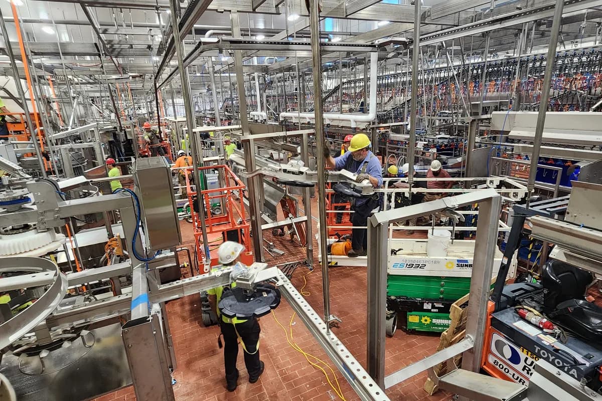
Plants rarely decide to upgrade their distribution. They run out of it, usually one added machine at a time, until the panels are full and nothing new can be connected without a plan. At that point the work is a design exercise well before it is an installation.
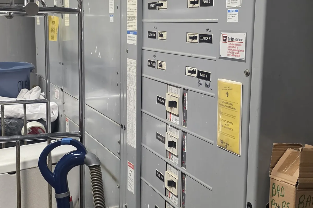
How a plant outgrows its distribution
Distribution grows by accident. A machine gets added and taps the nearest panel with space. A compressor gets its own subfeed off a subfeed. Somebody double lugs a breaker because the schedule showed a spare that had already been used. Ten years of that produces a system nobody can draw and nobody wants to touch.
The warning signs are consistent. Panels with no usable spaces left, breakers for gear that went out of production twenty years ago and has no replacement parts, voltage complaints at the far end of the building, lights dipping every time a large motor starts, and a main breaker sitting close to its rating during peak production.
The last one is the expensive sign, because it usually surfaces when the plant wants to add a line and finds out it cannot. Distribution work has lead times on gear and needs an outage to install, so a plant that waits until capacity is already gone pays in delayed production rather than in materials. It is the same pattern we see on smaller buildings through our electrical service upgrade work, with more zeros on it.
The load study comes before anything is ordered
Calculated load and actual demand are different numbers, and in an existing plant they can be very different. Article 220 gives the calculation method and is the right starting point, but a building that has been running for years can tell you the truth directly. Utility billing history gives demand over months, and a recording meter on the main over a representative period gives the shape of it, including shift changes, startup and the hottest afternoon of the summer.
Two things distort a study when they are skipped. The first is diversity, because connected load is always far larger than what runs at once, and sizing to connected load buys equipment nobody needs. The second is future load. An upgrade should carry the plant through the next expansion, which means asking what production intends to add rather than adding a round percentage and hoping.
The utility is the other half of the answer. Service capacity, the size of the utility transformer and available fault current at the service point all have to be settled early, because that conversation has a longer lead time than any piece of gear.
480V and where 120 and 208 volts come from
Almost every plant of any size distributes at 480V three phase, and the reason is current. The same power at a higher voltage means less current, so smaller conductors, less voltage drop over a long run and less impact when a large motor starts. Motors, compressors, drives and process equipment are fed at 480 wherever practical.
Everything else comes from step down transformers. Lighting often runs at 277 volts directly off the 480V system, while receptacles, controls, offices and small equipment come from 480 to 120/208 transformers placed near the loads they serve rather than all in one room. Keeping a transformer close to its panel keeps the small feeders short.
The transformer secondary is a separately derived system and the grounding rules for it are specific. One main bonding jumper, one grounding electrode connection at the source, and neutral and ground kept separate everywhere downstream. Getting this wrong puts neutral current on building steel, which shows up as noise on control and instrument circuits long before anyone traces it back to the transformer, as described in instrument racks and process signal wiring.
Coordination, so a fault trips the nearest device
Selective coordination means that when something faults, the device closest to the fault opens and nothing upstream of it moves. Without it, a failed motor lead on one machine shuts down a whole plant, and maintenance starts the shift working out which of several hundred loads caused it.
Coordination is a study, not an opinion. It compares the time current curves of every device from the service down to the branch, checks fuse ratios where fuses are used, and sets the adjustable trip units in the larger breakers so the curves do not overlap. It also has to account for the ground fault protection required on larger 480V services, which brings its own problem because sensing at the main can be faster than the breaker below it.
- Every protective device in the path needs to be on one coordination study, not chosen individually
- Interrupting ratings have to equal or exceed available fault current at each point of the system
- Adjustable trip units are worth nothing until somebody actually sets them and records the settings
- Ground fault protection at the service needs checking against downstream devices
- Record the final settings on the one line diagram, not just in the commissioning file
Phase identification and labelling
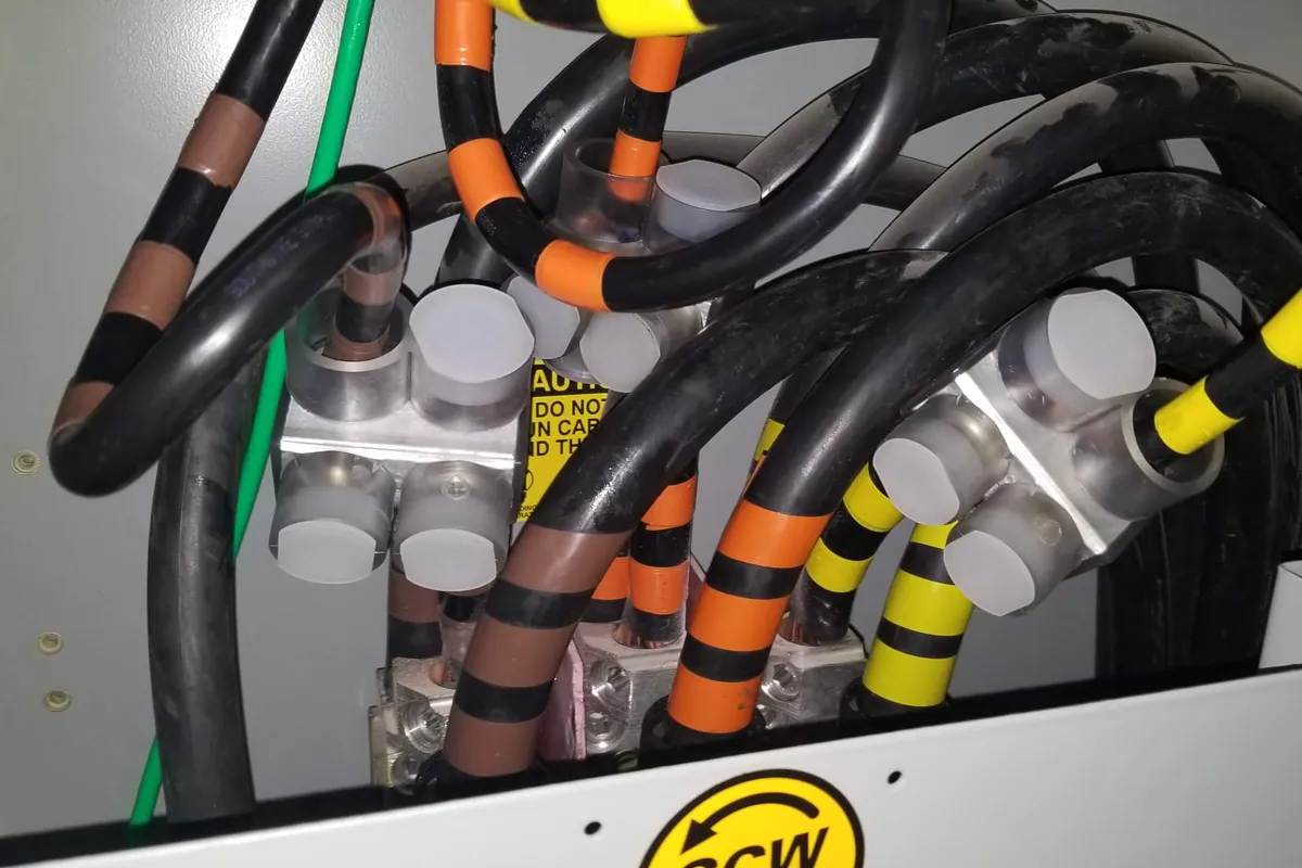
Phase colour coding is a convention rather than a nationwide rule, but consistency inside a building is close to mandatory in practice. The common pattern is brown, orange and yellow for 480 volts and black, red and blue for 120/208, with neutrals kept distinct between the two systems. Where a building already has a convention the new work matches it, because a mixed building is where mistakes happen.
The code does require the identification method to be posted at each panel where more than one nominal voltage exists, and it requires the high leg of a delta system with a grounded midpoint to be identified in orange. Large feeders get phase taped wherever they are accessible, at both terminations and in every pull box, because that is where a crew meets them later.
The rest of the labelling is what makes the system usable: panel schedules that reflect reality, feeders identified at both ends, a one line diagram posted in the electrical room and kept current, and equipment marked with its source. A plant that keeps this current gets far more out of a preventive maintenance program than one that does not.
Arc flash changes when the distribution changes
Upgrading distribution raises available fault current. A bigger transformer, a lower impedance path, shorter or larger feeders, all of it increases the current a fault can deliver. That has two consequences, and both belong inside the project rather than after it.
The first is equipment rating. Every device has an interrupting rating and it has to be at least the available fault current at its location. Equipment correctly applied before an upgrade can be underrated after it, which is a dangerous condition rather than a paperwork issue. The code also requires the available fault current and the date it was determined to be field marked at the service.
The second is the arc flash study. Incident energy depends on both available fault current and clearing time, so changing the distribution or the trip settings makes the existing labels wrong. NFPA 70E expects a review when a major modification occurs and at least every five years regardless, and the output is new labels, updated boundaries and revised procedures. That is covered in our arc flash and preventive maintenance post, with the thermal inspection that follows in the switchboard infrared survey. The installation itself nearly always happens inside a planned outage, run the way our industrial electrical services crews handle any shutdown scope.
Services used on this job
Got something like this coming up?
Tell us what the building is and what it has to run. We will tell you what it needs and what it takes. The phone is answered around the clock.